14.11.2025
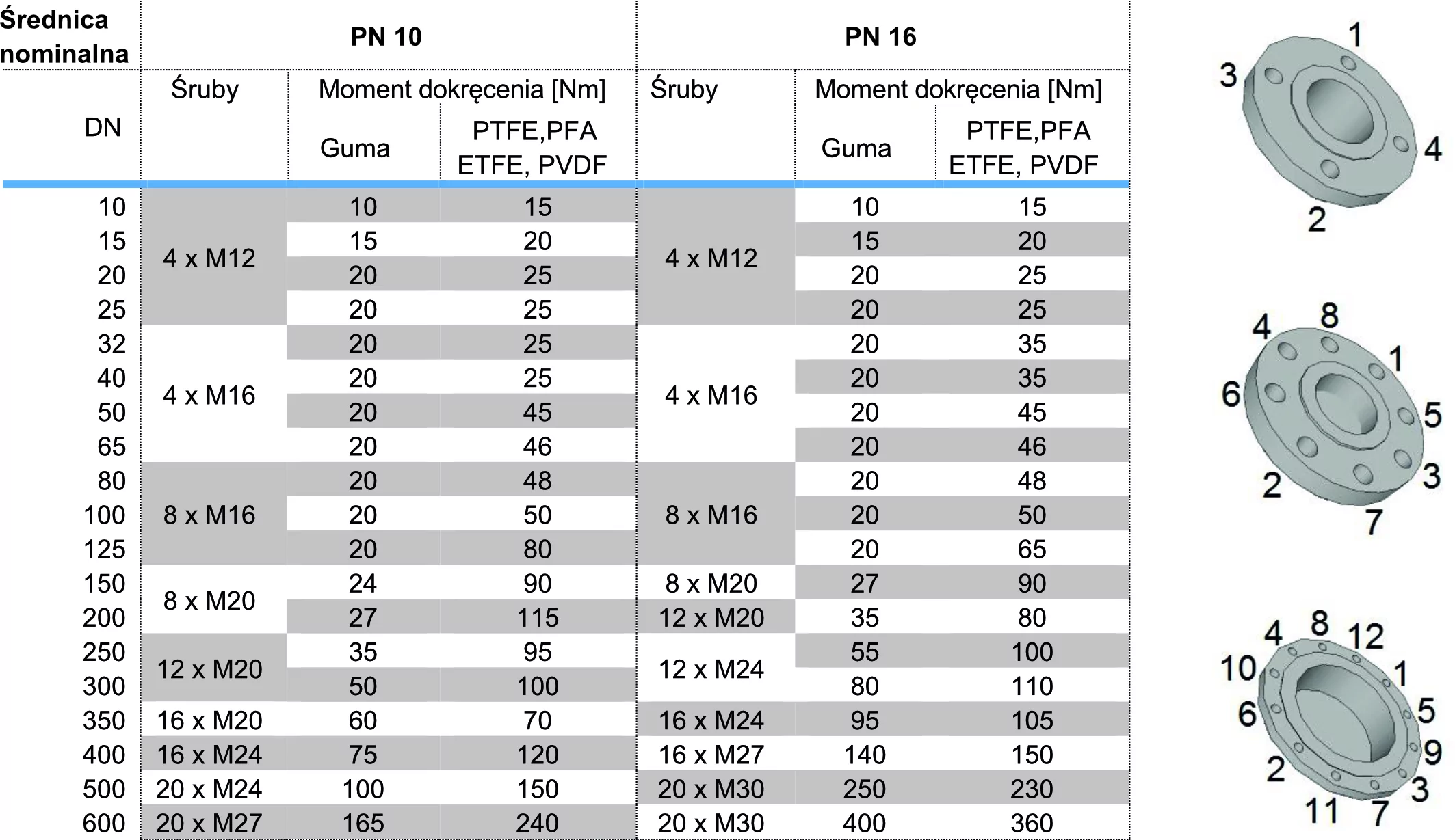
When configuring mounting components, we begin by determining the process connection. The standard connection for electromagnetic flowmeters is a flanged connection, but applications also include flanged, threaded, hygienic connections according to the DIN 11851 standard, or tri-clamp connections. However, even with the most popular and commonly used flanged connections, errors and mistakes can occur. It's important to remember that the flange configuration, i.e., the number, spacing, and size of the bolts, is determined by the DN diameter and the PN pressure standard. The table below shows what the flange will look like for a given flowmeter.
The most common errors occur in diameters DN150 and DN200, where when the pressure changes from PN10 to PN26 for DN150 the configuration does not change, while for DN200 there is a significant change in the number of screws from 8 to 12.
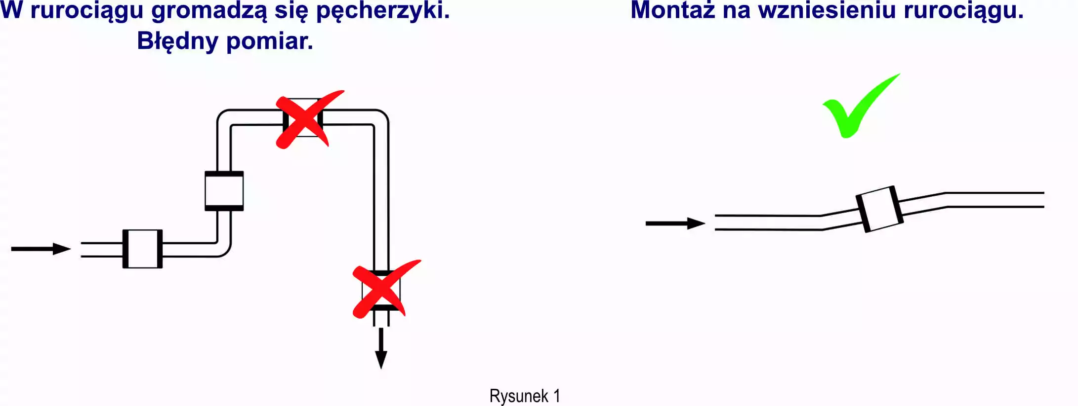
The next step is to properly select the flowmeter's installation location on the pipeline. This is crucial because flow through the full pipe is essential. Therefore, selecting the correct installation location is crucial. To avoid air bubbles, which can cause measurement errors or an empty pipe test alarm, the device should be installed before the pipeline rises, on the rise itself, or even on a vertical section with upward flow. Avoid mounting at the highest points of the pipeline or on a slope (Figure 1).
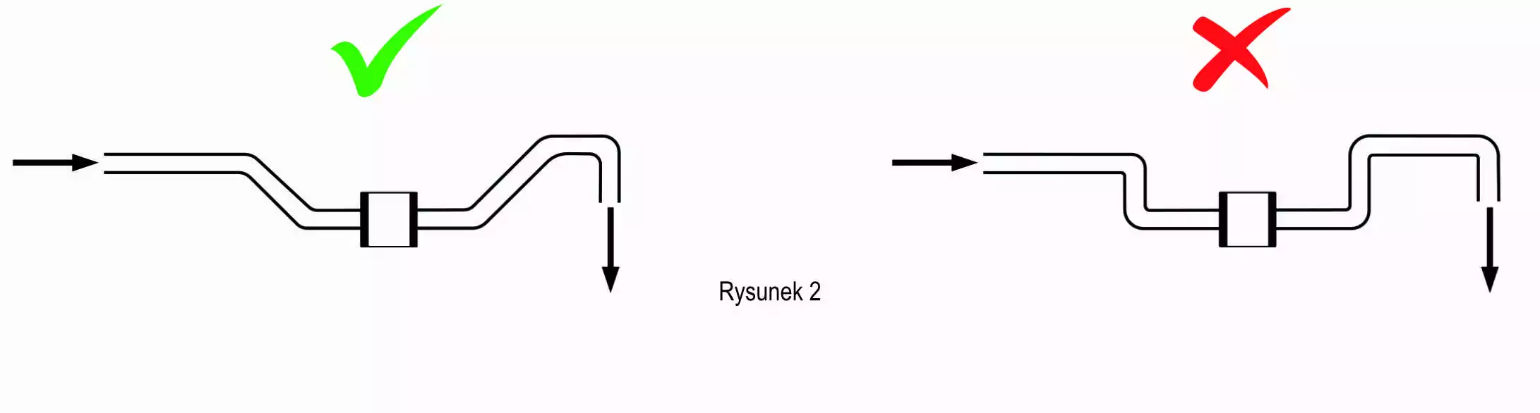
To ensure full flow through a full pipe, a flowmeter is sometimes "siphoned." In this case, it is important that the slopes and rises are smooth, not at 90°, but at a maximum of 45° (Figure 2).
Ensuring flow through a full pipeline is not the only challenge facing us in selecting the appropriate installation location. Various sources of interference occur during measurements with electromagnetic flowmeters. One of the most common interferences occurring during this type of measurement is the swirling of the medium in the pipeline, also known as cavitation. This can occur due to the aforementioned excessively rapid change in the pipeline cross-section or incorrect "siphoning." Other causes of cavitation include incorrectly centered seals during installation. However, one of the two most common causes of flow disturbances is installing the flowmeter too close to bends in the pipeline. Therefore, to calm and even out the flow of the medium, it is recommended to use straight sections upstream of the flowmeter, 5 times the flowmeter diameter, and downstream of the flowmeter, 3 times the flowmeter diameter.
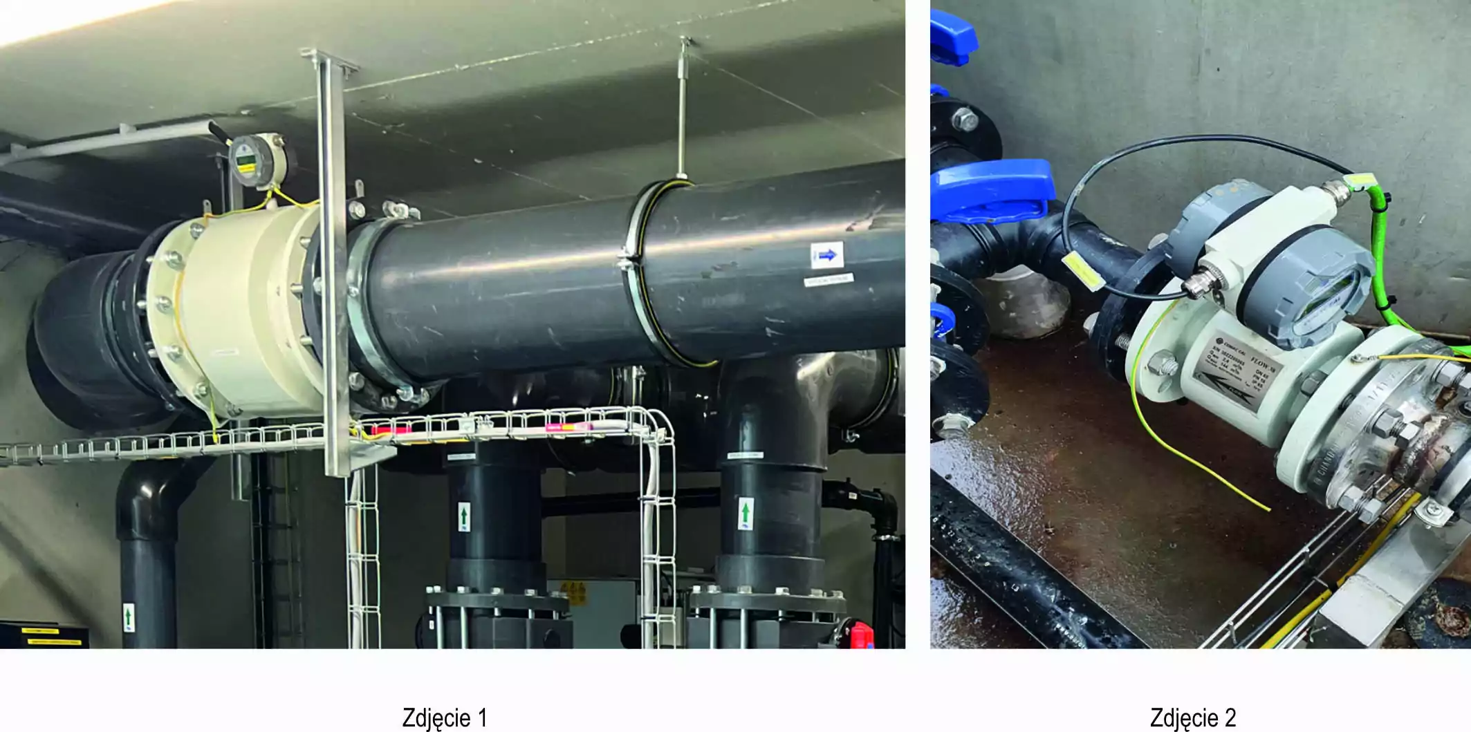
For even better flow stabilization, X-shaped pipeline inserts can be used. Examples of incorrect flowmeter installation are shown in photos 1 and 2.
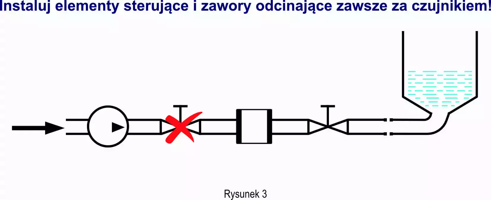
The second most common cause of cavitation is the installation of flow meters directly after control elements such as gate valves, valves, dampers, etc.
Another, often overlooked issue that can also affect measurement is pump-induced vibrations. Therefore, the flow meter should always be supported and damped with a soft material, such as a rubber pad. Vibration dampening is important in the context of fluid flow disturbances. In addition to damping vibrations caused by the pump, the pump side is also important. The flow meter should NEVER be mounted on the suction side of the pump. The vacuum generated by the pump can damage the flow meter lining, causing damage, and can cause flow through an incomplete pipeline. As previously mentioned, this causes significant measurement error.

Another important source of interference resulting from measurement technology is an excessively intense electromagnetic field, which can affect the electromagnetic field in the flowmeter sensor and induce an incorrect voltage relative to the flow.
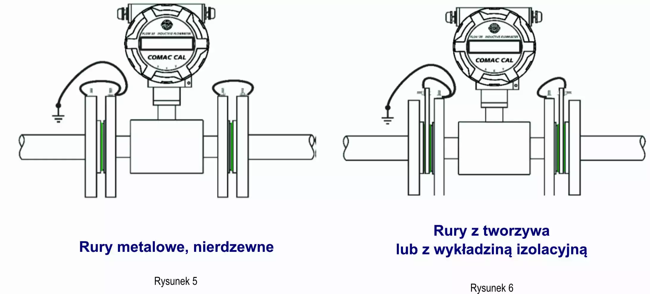
The final, crucial element of electromagnetic flowmeter installation is proper grounding. To equalize the electrical potential, the flowmeter flanges should be grounded to the pipeline flanges and connected to ground (Figure 5). The situation is slightly different when flowmeters are used on plastic pipes or those with insulating linings, for example, after pipeline renovation using plastic spraying. In such cases, grounding rings must be installed between the flanges (Figure 6).
After determining the location and method of mounting the measurement sensor, it remains to determine the location of the flowmeter's electronics, i.e., the display. Besides access to the display, it's also important to ensure the electronics are mounted in a location where there's potential for flooding. If possible, there are two ways to protect the electronics: either increase the electronics' sealing or move it away from the sensor, away from the potential flooding zone. The standard configuration with the display mounted on the sensor has an IP65 sealing rating. This can be optionally increased to IP67. This is the maximum possible sealing rating for a configuration behind the integrated display. IP68 is also possible, but only for the sensor itself in a configuration with a remote display. This sealing rating also allows the flowmeter to be buried underground, but it should be remembered that the standard powder-coated 304 carbon steel housing is not suitable for burying. In such cases, the paint should be changed to a special epoxy paint or the housing should be replaced with 316L stainless steel. For the disconnected version, we have the option to change the display type.
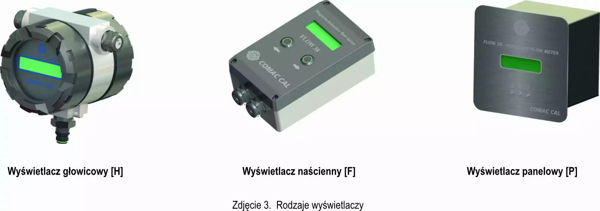
A standard head-mounted display (H) requires an angle bracket, which can complicate installation. Therefore, in this case, a wall-mounted display (F) may be a better choice, as it can be mounted on a hook on the wall or on a TH35 rail in an electrical cabinet. Another cabinet-mounted solution is the panel display (P), which is designed for mounting in a hole in the interior door of an electrical cabinet. The tightness of both the wall-mounted and panel-mounted displays is IP54. Assuming that moving the electronics away from the sensor removes them from the potential flood zone, this tightness is completely sufficient.
Because the passive signal from the sensor is processed within the electronics, the supplied flowmeter is calibrated with its cable. Therefore, the cable cannot be extended or replaced. It is also important to avoid running it near power cables, as additional voltage can be induced in the signal cable, which can cause measurement errors. The signal from the sensor to the electronics is measured in mV, so a small voltage change can have a significant impact on the measured flow rate. The supplied cable is adequately insulated and shielded. However, running it near a power cable, for example, a high-power pump, may not be sufficient to suppress interference.
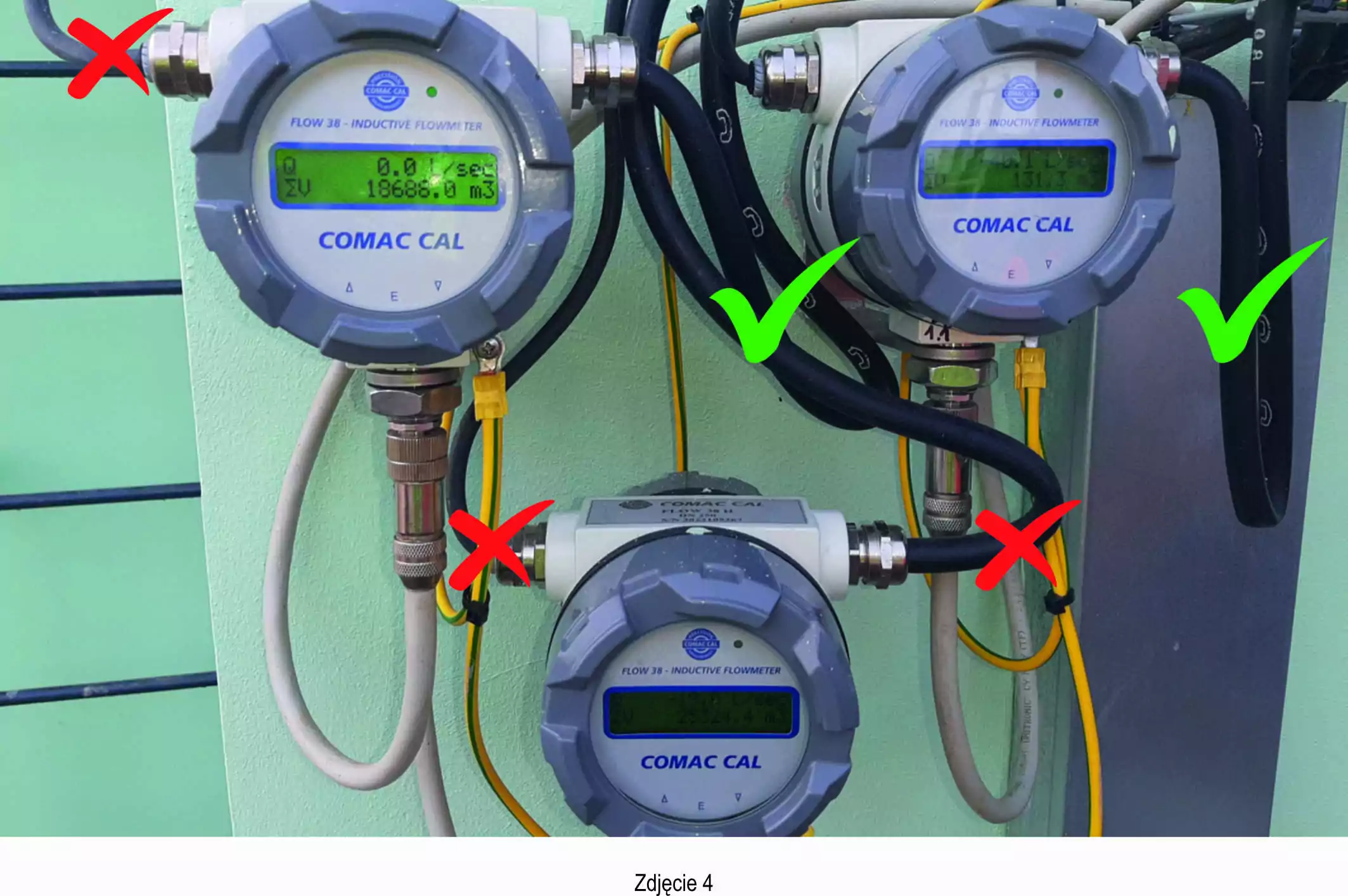
Often, it's the cables, or rather their proper connection to the displays, that can impact the system's tightness. Besides properly tightening the cable gland, cable routing is also crucial. It's good practice to leave a slack in the cable before approaching the gland so that water can drain freely. Running the cables from the top to the gland can cause water to accumulate near the glands. Water penetrates even very tightly tightened glands and can cause moisture to penetrate the electronics, which can quickly damage the flowmeter. An example of both correctly and incorrectly routed cables is shown in Photo 4.
Thanks to their measurement technology, electromagnetic flowmeters are versatile, reliable, and highly accurate, making them suitable for a wide range of applications. This doesn't mean they're suitable for every measurement, but they are undoubtedly the most popular type of flow measurement device. We hope the above information will be helpful in properly installing flowmeters so that the installed devices operate with the highest precision and reliability for many years to come.
Our offer includes electromagnetic flowmeters from the Flow series from the Czech manufacturer Comac Cal. One of the most popular is the classic Flow 38 electromagnetic flowmeter, which is also available with MID. An IoT telemetry module is available for the Flow38, enabling remote access to measurement data via a web platform.
Another popular electromagnetic flowmeter model is the battery-powered Flow45 electromagnetic flowmeter. This year's new product is the Flow55 for pipes not fully filled. Check out the Flow series electromagnetic flowmeters in our online store at czujniksterowniki.pl
Please note that the prices presented in the online store are indicative for selected parameters. Due to the large number of possible combinations, please contact us for an accurate quote.
07.11.2025
We have already delivered nearly 1,000 electromagnetic flowmeters to our customers. The experience we have gained has shown us the most common problems encountered by designers, installers, and users of these devices. In this article, we will focus on the proper selection of an electromagnetic flowmeter.
25.04.2023
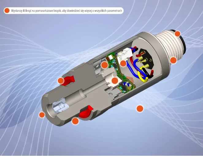
This interactive graphic provides a brief overview of the key components of the pressure transmitter. Click on the red dot to learn more about the item.
22.05.2024
We invite you to the conference "FLOW MEASUREMENT: CHALLENGES - TECHNOLOGIES - SOLUTIONS". This year's edition of the Poltraf conference will be held in Gdańsk on October 2-4, 2024.

We are a representative and distributor in Poland of the following brands:

since 1994
since 2004
since 1997
since 2010
since 2009
since 2016

since 2023

since 1994

since 1994

since 2001
od 2024 r.
 Unit Calculator